Introduction
- Login
- Select user alignment file
- Insert the specimen holder
- Adjust the high tension: Select HT box in Head panel which opens a menu in the Center panel. Select the HT radio button. Select a step size of 0.5 KV to increase or up to 5 KV to decrease the HT setting.
- Turn on the Beam Current
- Align the filament: Select Spot Size 1 in the Left menu panel and Magnfication of 2000x. Focus the beam to crossover and center using the Beam Shift. In the HT/Beam/Fil menu in the center panel, select the Fila. Current radio button and desaturate the filament. Make the filament image symmetrical using the Gun Align Tilt control in the Center menu panel.
- Align the gun and condenser aperture: Select Spot Size 3 or 4. Focus the beam to crossover and center the beam using Beam Shift. Select Spot Size 1 and center the beam using Gun Align Shift. Repeat until beam is centered under both conditions.
- Correct condenser lens stigmation: Set Mag to 5000x, Spot Size to 3, and focus beam to crossover and center on screen. Depress selector button 2 (CL Stigma) on FB and correct the “roundness” of the filament. It may be very much easier to accomplish this adjustment on a desaturated filament.
- Center the condenser aperture: When the condenser aperture is centered the beam will expand and contract at the center of the screen as is passes through crossover. If it sweeps from side to side the aperture needs to be centered using the X/Y adjustment knobs on the aperture.
- Adjust Z height: Set magnification at 5000x or higher. Focus the image. Select Z Cont from the left hand menu. Select Auto from the Z control central menu. Confirm the image is focused. Then Click on OK in the popup window.
- Adjust Voltage Center: Select magnification of 20,000x or higher and locate a small feature in the specimen and bring to the center of the screen. Select Beam Tilt on the Center menu, press Align Wobb selector button on FB and determine if the small feature moves. Minimize movement by dragging the mouse. Turn off Align Wobb.
- Center the Objective Aperture: Insert and center a Selected Area Diffraction aperture. Depress Diff button and set Mag/Cam L to 50-100 cm. Focus diffraction spot using Diff Focus. Center the diffraction spot using PLAlign. Insert objective lens aperture and center it around the diffraction spot using the X/Y adjustment knobs. Remove the Selected Area Diffraction aperture from the beam and return to Mag function.
- Correct objective lens stigmation: Set magnification at 50,000x or higher. Depress OL Stig button on FB. Focus the specimen and observe Fresnel fringe. Drag the mouse, usually in a circular motion, to adjust Fresnel fringe. If the image shifts, use the selector 1 button to recenter the image.
INTRODUCTION DETAIL: The JEM 1230 needs minimal optical alignment under normal day-to-day operating conditions. Each user will have in their user profile alignment configurations for various accelerating voltages. However, precise tuning of the alignment, based on magnification, apertures selected, and other specimen-specific conditions, is suggested to obtain the best results. The following procedure, adapted from the recommendations of the JEOL Institute and Dave Harling, is provided as a guide.
Conventions used: Select means to use the mouse left button to click on the described menu, selection box or radio button. Push means to depress a physical button on the Function Box (FB) to the left of the column. Menu regions on the JEOL CRT are the Head menu (the topmost region), the Left menu (default menu has User Name at top), the Center menu (default menu has Mouse Drag at top), and the Right or Main Menu Screens. Non-default menu screens have a box with a horizontal bar in their upper left corner. Selecting that box closes the window. Alignment functions performed by dragging the mouse on the desktop always require the right button be depressed and a mouse drag function to be selected and displayed in the Mouse Drag SW window or a selected (green-filled) box in a menu.
LOGIN DETAIL: Select Login from the Right Menu. In the Center Menu select the User Name input box and type your user name and push Enter. Select the Code No. input box and type your password and push Enter. Select Apply. (First time users will not have a Code No. assigned, so skip that step. You may enter a Code No. of up to 4 characters or digits of your choosing later. (To enter your code from the Main Menu select Setup, then Users, then in the Center Menu select Change Over Code No. Leave Old Code No. box blank and enter desired Code in the two remaining boxes. Remember to press Enter after each entry. They Select Apply and close the window.) See Libby or Bob if your login fails, if you forget your password or if you do not yet have a user account on the microscope.)
PERSONAL FILE DETAIL: Select Personal File from the Main Menu panel. Select Align File from the Main Menu panel. The File List will open in the center panel. Select the radio button to the left of the appropriate alignment profile. Select Function Load from the Center menu. Close the window. Most of the alignment procedure will be done automatically by loading an Alignment file for the specific KV you will be working. Some operating conditions, including the high tension, are not saved in the profile. Only minor touch-ups may be required. If you make an "inappropriate" adjustment during the alignment, reload your alignment file.
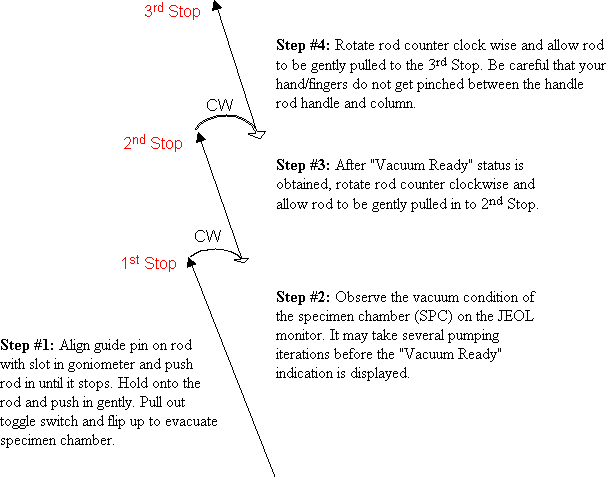
SPECIMEN HOLDER DETAIL: Load a holey carbon or calibration grid in the specimen holder. (For details on loading specimens into specific rotational holders, see Hex Ring Holder or Gimble Holder.) In the right Monitor Panel, select Monitor and Vacuum conditions. In the Center panel observe the readings for the specimen chamber (SPC). The goniometer has indicator lights that could also be used to monitor the vacuum condition of the SPC, but the use of the Monitor is preferred. Follow the schematic below (from bottom to top) to insert the specimen into the beam path.
When using the Gimble (±110°) or Hex Ring (360°) rotational holders, they must be connected to their respective controllers. The cables and connector pins are unique for each and the controller boxes are labeled. Support the cable to minimize transmission of vibration to the specimen holder.
HIGH TENSION DETAIL: Under normal operating conditions, the high tension is left on at 100 KV 24/7 and you may not need to change it. In the Head panel the current HT setting is displayed (normally in black with “Ready” text to the right of the value. Beam current display in the Head panel will indicate a value (~57 uA at 100 KV). If you want to change the HT, select HT box in Head panel which opens a menu in the Center panel. Select the HT radio button. Select a step size of 0.5 KV to increase or up to 5 KV to decrease the HT setting. Repeatedly and slowly click on either the Up or Down button to adjust the HT as desired. Proceed slowly allowing the HT indicator to stabilize (turn black) and Ready to be displayed in the H panel. The beam current should change in the same direction as the change in HT.
If the HT is turned off for some reason, (indicated by orange KV setting value and no Ready message) proceed as described above to increase or decrease the desired KV. The selected KV will be displayed in the center menu panel to the right of the HT radio button. When the desired HT is displayed, select the On radio button. The beam current will increase slowly and the KV indicator will turn black and the Ready indicator will be displayed.
BEAM CURRENT DETAIL: In the HT/Beam/Filament Control Center menu (visible only after selecting the HT button from the Head menu), confirm that the Beam setting is about 10 uA. Select the On radio button in the center menu OR in the Left panel Beam Curr: box.
a.Confirm that the objective lens aperture is removed (bar at bottom of knob pointing toward the front of the column).
b.Set the magnification to ~1500x using the Mag toggle switch on FB. The magnification is displayed in the top left side of the Head panel of the CRT.
c.You should see the electron beam on the fluorescent screen. If not, Press the STEP button above the Brightness knob on the FB to light the former and rotate the Brightness knob while observing the fluorescent screen. The beam should become visible.
d.If you still cannot see the beam, confirm (1) the objective aperture is removed, (2) the beam current is higher than the dark beam current (~65-69 uA at 100 KV), (3) Spot size 1 in the Left menu panel is selected, and (3) that the specimen has not be inserted fully into the column. If the specimen is in the column and you don’t want to remove it, lower the magnification and center the specimen grid in the beam path. (On the Left menu screen, select Spc Pos, on the next Left menu select Point On, then click in the center of the grid displayed in the menu. If the grid was blocking the beam, you might see the beam as the grid moves.)
e.If you still cannot see the beam, Reload your Alignment file.
ALIGN FILAMENT DETAIL: Select Magnification of 1500-2000x. Select Spot Size 1 in the Left menu panel. Adjust the Brightness knob on FB to focus the beam at crossover. Center the beam on the screen by pressing the Beam Shift button on FB and depressing the right mouse button while dragging the mouse. In the HT/Beam/Fil menu in the center panel, select the Fila. Current radio button and use the Down value control to desaturate the filament. (Each click of the mouse button on the Down button desaturates by the amount shown in the Step box. It may be necessary to change the Step value to obtain suitable results. The value cycles upwards through the available values with each click of the mouse in the Step button then returns to the minimum value.) Select the Gun Align Tilt control in the Center menu panel and drag the mouse to make the filament image symmetrical. Symmetrical does not mean “round,” but the black filament image should be centered in the bright beam spot. Resaturate the filament by increasing the filament current.
GUN AND CONDENSER APERTURE DETAIL: Select Spot Size 3 or 4 in the Left menu. Press Beam Shift on FG and focus the beam to crossover and center the beam dragging the mouse while depressing the right button. Select Spot Size 1 in the Left menu. Select Gun Align Shift in the Center menu (HT/Beam/Filament) and recenter beam dragging the mouse with the right button depressed. Alternate centering the beam using Spot Size 3/4 and the Beam Shift or Spot Size 1 and Gun Shift until the beam is centered under both conditions. CONDENSER LENS STIGMATION DETAIL: Set Magnification to 5000x, Spot Size to 3, and focus beam to crossover and center on screen. Select Setup, then F1/F2 Key on the Main Menu screen. Select CL Stigma under F2 column in center menu. Depress selector button 2 on FB (it lights) and correct the “roundness” of the filament with by dragging the mouse with the right button depressed. “Roundness” is subjective and it may be easier to correct the condenser lens astigmatism by “focusing” the filament image. Begin by desaturating filament. With the FB 2 button depressed, drag the mouse to make “hairs and blobs” in the filament image sharp while focusing the filament image with the Brightness knob. Resaturate the filament. Close the HT menu. Depress the Beam Shift button on FB.
CENTER CONDENSER APERTURE DETAIL: The beam will expand and contract at the center of the screen when the condenser aperture is centered. If it sweeps from side to side the aperture needs to be centered. Focus and center the beam on the screen. Turn Brightness Step on. Slowly focus the beam back and forth through crossover. Use the “corner marks” on the screen to determine if the outer edges of the beam are in the same location on both sides of crossover. If the outer edges are not even, use the X/Y adjustment knobs on the condenser aperture while continuing to focus through crossover to center the aperture and the beam.
CENTER OBJECTIVE APERTURE DETAIL: Insert and center a Selected Area Diffraction aperture (lowest aperture holder on the column). Select Align Adj from the Main menu the select PLAlign from the bottom of the Center menu. Depress Diff button on FB and set Mag/Cam L to 50-100 cm with the Mag toggle switch as revealed on Head Menu on the monitor where magnification is usually displayed. Use the Diff Focus knob on FB to focus the diffraction spot to its smallest diameter. WORK QUICKLY; YOU DON’T WANT TO BURN THE SCREEN! Center the diffraction spot on the screen by dragging the mouse with the right button depressed. Insert the desired objective lens aperture and center it around the diffraction spot using the X/Y adjustment knobs. Remove the Selected Area Diffraction aperture from the beam and return to Mag function.
CORRECT OBJECTIVE STIGMATION DETAIL: Astigmatism results in “elongation” or smearing of objects in the image which significantly degrades resolution and must be corrected. Although the objective aperature and lens are the primary sources of astigmatism, nickel grids, and the location of the beam with respect to the grid bar or edge, can dramatically affect image quality. Astigmatism in a TEM is not affected by magnification, so it always corrected at the highest magnification possible. Set magnification to 50-80,000x. On the Menu screen, select Setup then F1/F2 Key. Select Image Shift for f1 and CL Stigma for f2. Depress (and light) OL Stig selector button on FB. Focus the specimen carefully and observe Fresnel fringes (around small holes) or small particles (from carbon evaporation, gold or ferritin particles). Drag the mouse, usually in a circular motion, with the right button depressed to adjust Fresnel fringe. If the image shifts, press the selector 1 button on FG and drag the mouse to recenter the image. When you’ve finished, press the Beam Shift button on FB.